Working with the good folks at Impact Technologies LLC in Tulsa, OK gave Systems of Merritt, Inc. the opportunity to work on five different control systems. Four of the systems were designed, built and programmed from scratch and one existing controller was reprogrammed.
The systems being controlled ranged from VFD/electric motors, high pressure pumps, hydraulic motors and pressure vessels.
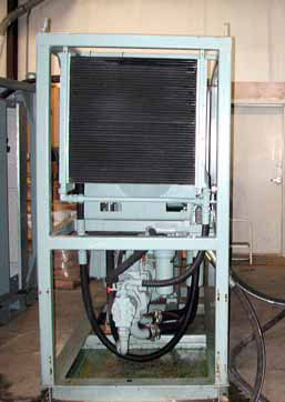
The image below shows one of the systems. A hydraulic pump is driven by a 200hp electric motor. A servo-valve interfaced to a control system regulates the flow to the hydraulic motor (on another skid). The hydraulic motor drives a three-stage high-presure slurry pump. Feedback sensors included a rotary encoder measuring the position and angular velocity of the hydraulic motor shaft. A pressure sensor is used to measure the output pressure of the high-pressure slurry pump.
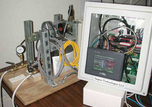
The image below shows the control box for another system which includes VFD/electric motors, a slurry pump, valves and a density measuring transducer. The structure behind the control box is a system simulator used to test the control box functions.
The system simulator is made up of a small electric motor, VFD, water pump, pressure sensor and optical rotary encoder. The hoses leaving the simulator, on the left , go to a bucket containing fluid to circulate through the water pump. The VFD simulates the input to several of the systems, including sevo-valves and linear actuators. The optical rotary encoder and pressure sensor are the same types as used on the actual systems.
The use of the simulator allows extensive testing of control loops and HMI functionality without having to use time on the full-scale systems. For safety reasons, some of the simulator tests cannot be carried out on the full-scale system, but are vital for testing for failure modes and conditions.
The HMI was developed on a Maple Systems color touch-panel display. Screen shots are shown below to illustrate some of the features of the HMI.Three pages of dials, alarms and controls, illustrate some of the features of the controller.
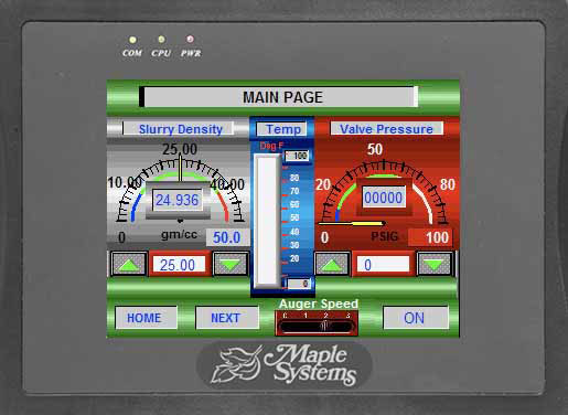
The most important controls are on the main page below. Slurry density, valve pressure and temperature are displayed on the two dials and bar in the center. The up and down arrows control the desired settings (displayed between the arrows) for density and pressure. The desired settings can also be changed by a pop-up keypad when the display box is touched.
Each of the two dials can have low and high warnings, indicated by the multi-colored stripe on the inside of the dial tic marks. The dial scale can also be adjusted by changing the dial maximum settings. A four position auger speed control is at the bottom of the screen. The temperature range can also be adjusted by changing the minimum and maximum values on the scale.
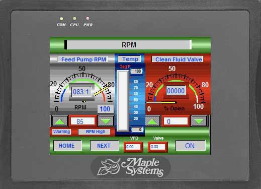
The second screen shown below features dial displays for pump RPM and percent valve opening. A warning is displayed under the RPM dial indicating a value above the high alarm setting. You can also see that the dial pointer is in the red sction of the dial stripe, which marks the high RPM warning range.
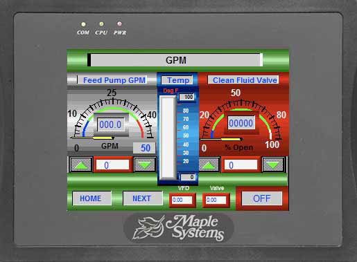
The third screen shown below features a GPM (gallons per minute) dial beside the same percent valve open dial as on the previous screen. The GPM and RPM are related by a ratio.
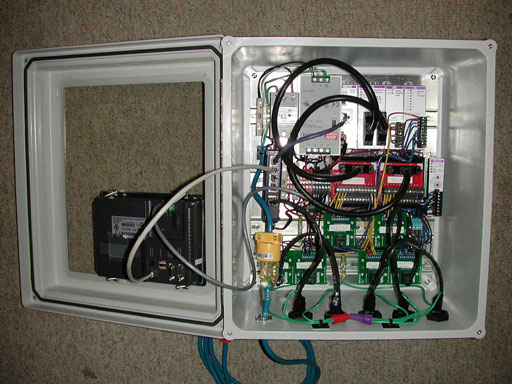
The closed-loop controller, made by Delta Computer Systems, is in the upper right section of the control box pictured below. To the left of the Delta controller are power supplies, and the remainder of the box is taken up by breakout boards and connectors. The I/O for the box (at bottom of image) is handled by Cat-5 cables and connectors.